
Airports are places where Aircraft can land and take off having terminal buildings for passengers and facilities of all kinds for travel. Airport is a Civil Engineering structure consisting of runways, taxiways, aprons, hangers and buildings that make entire operations of aviation possible.
Classification of Airports as per ICAO
ICAO : International civil aviation organization
Type A : Basic runway length = 2100 m or above and width of pavement = 45 m
B : Basic runway length = (1500 – 2099) m and width of pavement = 45 m
C : Basic runway length = (900 – 1499) m and width of pavement = 30 m
D and E : For small airports.
Similarly ICAO provides code number from 1 to 7 that denotes single isolated wheel load and Tyre pressure.
Code 1 : Tyre pressure is 8.5 Kg/Cm2
Code 2 : Tyre pressure is 7 Kg/Cm2 and So on
Introduction to Airport Surfaces
Here we will see how many types are surfaces are considered while designing the Airport Runways and Taxiways. These surfaces play a pivotal role in specifying the obstructions that may hamper the functioning of airport.
Airport Obstruction
- Imaginary Surfaces in Airport
- Object with actual height
Imaginary Surfaces in Airport
No obstructions should project on imaginary surfaces of Airport for safe flight operations. They are fictional surfaces projected over runway for analysing conditions for safe landing and takeoff without disturbance.
- Approach Surface : Trapezoidal, Longitudinally centered on extended centre line of runway, on each end.
- Conical Surface : Circular in shape with side slope in upgrade direction.
- Horizontal Surface : Extend from upper edge of transitional surface to inner lower circular edge of conical surface.
- Transitional Surface : Trapezoidal, side slope, extend along landing strip and upto part of approach surface
- Take off climb Surface : Trapezoidal, on take off side, it has upgrade near extremity of runway. Its side diverges away.
Clear Zone : innermost portion of approach zone. It is to be provided at ends of runway.
Turning Zone : Intended for turning operation of aircraft in case of emergency.
Object with Actual Height
Any Object within 45 km range from runway end is considered obstruction if its height H > 30 m or H > level of approach end.
For Object beyond 4.5 km, if its height above 30 m increase by more than 7.5 m for each additional 1.5 km.
or H> 75m within 15km distance from runway end.
If Object height > 150m above ground. (project above minimum approach flight altitude)
Design of Airport
In this section we will see how the airport runways, taxiways and terminal areas are designed and come to know about various factors we need to consider while designing it.
Runway Design
Airport Wind Rose Diagram
Used for alignment of runway along Head wind. Cross winds tend to destabilize the flight operations. Cross wind component interrupt safe landing and takeoff operations so it should be minimum.
Vsinθ should not be greater than 25 km/h.
Wind Coverage : Percentage of time in year in which cross wind component remain within limit of 25 Km/h.
For Runway : minimum 95 % of wind coverage required.
For wind rose diagram, average wind data of 5-10 yrs are collected and represented as chart.
Type 1 Plot : direction and duration of wind
Type 2 Plot : direction, duration and intensity
We measure wind speed in all directions and plot it radially on circular diagram in which directions are labeled. Then we connect plot points representing wind velocity with straight lines to form closed polygon.
Then we measure diagonals along each direction line.

The best direction is represented by longest line in wind rose diagram.
Eg. In this case NNE – SSW is longest so, runway orientation will be in this direction.
Calm Period : for period in which V < 6 Km/h
Airport Basic Runway Length
Assumption
- No wind blowing
- Fully loaded aircraft
- Sea level
- Zero off gradient
- Standard Temperature (15˚C)
Airport Landing Case:
Normal Landing

Normal Takeoff


Stopping in Emergency
Engine failure case. TOD become actual distance required to reach the height of 10.5 m with no percentage applied.
Called accelerate stop distance.
require clearway, stopway or both.
Note : The Case giving longest runway length is recommended
Correction to basic runway length
[1] Correction for elevation
As per ICAO basic runway length should be increased at the rate of 7% per 300 m rise in elevation above mean sea level.

[2] Correction for Temperature
At the rate of 1% per 1˚C rise in airport reference temperature above standard atmospheric temperature at that elevation.
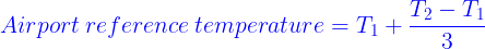
T1 = Monthly mean of average daily temperature for hottest month of year.
T2 = Monthly mean of maximum daily temperature for same month.
Standard temperature for airport : reducing mean sea level (15˚C ) at the rate of 6.5 ˚C per 1000 m rise in elevation.

As per ICAO, if total correction for elevation and temperature is greater than 35% of basic runway length, model test of site and specific study has to be adopted.
[3] Correction for Gradient

Should be increased at the rate of 20% for every 1 % of effective gradient.
Applied after elevation and temperature correction.

Geometric Design of Runway
Longitudinal Gradient
Airport Class: A,B,C – Max 1.5 %
Airport Class: D,E – Max 2 %
Effective Gradient
A,B,C : Max 1%
D,E : Max 2%
Rate of change of longitudinal gradient per 30 m length
A,B Type : 0.1 %
C Type : 0.2 %
D, E Type : 0.4%
Distance between two successive points of grade intersection:
D = 75(a + b) m
Minimum width of safety area = 300 m (Instrumental rule), 150 m (A,B,C), 78m (D,E)
Sight Distance : Any 2 points 3m above the ground should be mutually visible at distance half runway length.
Transverse Gradient
A,B,C : Max 1.5%
D,E : Max 2%
It should not be less than 0.5 percent for due to drainage purpose.
Runway Width : (18m to 45 m)
Taxiway Design
Taxiway provides access from runway to terminal area and service hanger.
Max. Longitudinal gradient : 1.5 % (A,B) , 3 % ( C,D,E)
Rate of change of longitudinal gradient (max.) = 1 % (A,B,C), 1.2 %(D,E)
Transverse gradient (max.) = 1.5 % (A,B,C), 2 %(D,E)
Turning Radius
\large\color{blue} R= {\frac{v^2}{127f}}R: Radius (m)
V : speed of aircraft (Km/h)
f : coefficient of friction (0.1)
\large\color{blue}R={\frac{0.388W^2}{0.5T-S}}R : Radius of centre line (m)
W: wheel base of aircraft (m)
T : width of taxiway pavement (m)
S : Distance between point midway of main gear and edge of pavement (m)
S : Oleo distance + T‘/2
T‘ : Tread of main landing gear (m)
Minimum turning radius of supersonic jet : 180 m
Note : Take maximum of above three cases
Width of Taxiway : 7.5 m to 22.5 m
Exit Taxiway : Minimize runway occupancy by the landing aircraft.
Angle of turn : (30˚and 45 ˚)
Widened entrance of 30 m tapered to normal width.
Length of entrance curve L1
\large\color{blue}{{L_{1}}}={\frac{v^3}{45.5CR_{2} } }Length of Central curve L2
\large\color{blue}{L_{2}}={\frac{\pi R_{2}D_{2}}{180} }C = 0.33
D2 : Deflection angle = Total angle of turn – D1
D1 : Deflection angle of entrance curve
Loading apron : Paved area adjacent to terminal building for loading and unloading operations.
Holding apron : Portion of paved area adjacent to runway ends (warmup, runup pad)
Terminal area
Gate Capacity
\large\color{blue}{G}={\frac{CT}{U}} \large\color{blue}{C}={\frac{UG}{T}}G : No. of gates
C : Design volume of capacity of gate in aircraft per hour per arrival/departure.
T : Weighted average gate occupancy time in hour.

U : Utilisation factor (0.6 -0.8)
Capacity of Gate (arrival + departure) = 2 X C (Operation per day)
For restricted gate use, minimum gate capacity is taken (each gate has its own gate capacity)
Visual Aids : Visual information, safe landing locate particular feature, orderly flow of aircraft.
Airport Markings and Lightings
In this section We will deal with several Airport markings that guide the passengers and aircrafts as well as elaborate system of airport lightings. We will also learn about Air traffic control.
Airport Marking
Runway (white) ; Apron, Taxiway ( yellow)
- Apron marking : Maneuvering and guide line path of nose gear of aircraft.
- Landing direction indicator : Arrow or Tee on centre of segmented circle; orange or white painted.
- Runway marking : Centre line, edge stripes, numbering
Touchdown marking (1.8m wide) : series of stripes
Numbering indicates magnetic azimuth [9 – 90˚ (W); 27 – 270˚ (E-W)]

- Shoulder marking : Yellow, diagonal stripes at right angle with direction of travel; blast pad (Chevron pattern)
- Taxiway marking : 15 Cm yellow stripe centre line, holding line marking at intersection.
- Wind direction indicator : Wind cone placed with segmented circle with landing direction indicator.
Cockpit Cutoff angle : angle between longitudinal axis of fuselage and an inclined plane below which the views of pilot are blocked by some sort of aircraft.
More cockpit cutoff angle – More the pilot can see the ground.
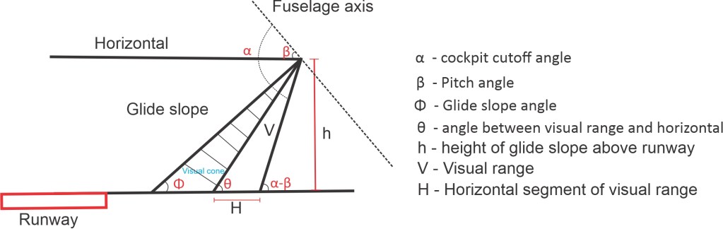
\color{blue}H={V\cos \theta - h\cot (\alpha -\beta )}\color{blue}{\sin \theta }={\frac{h}{V}}Airport Lightings
[1] Airport Beacon : strong beam of light that indicate geographic location slightly above horizontal and rotated to produce flashing light to observer.
Mounted on top of terminal building or hanger.
White or green flashes.
[2] Approach lighting : Sequence of high intensity lighting before runway starts.
Calvert system or ICAO system.
[3] Apron and hanger lighting : Flood lit
[4] Boundary lighting : on fence
[5] Runway lighting : narrow gauge lighting and edge lighting (white)
[6] Taxiway lighting
[7] Threshold lighting : green light line at large airport across entire width of runway.
On direction of landing : Green
Opposite direction : Red
Decision Height : lowest height above the runway where pilot make decision to continue landing or not. (30 m – 75 m)
Air Traffic Control
Two basic flight Rules :
[1] IFR (instrumental flight rule)
[2] VFR (Visual flight rule)
VFR : Prevail in good weather condition when aircraft can maintain safe distance by visual means.
IFR : Prevail when visibility or ceiling falls below prescribed by VFR. Responsibility falls under Air traffic control and they assign specific route and altitude.
Heliports and Stolports
VTOL : Vertical take off and landing
STOL : Short take off and landing
UASI : Visual approach slope indicator used at Stolports
A vehicle requiring 900 m or less of runway can be considered as a STOL aircraft. It requires powered lift for its operation rather than relying entirely on the mechanical lift.
Advantages of STOL aircraft
- Intercity transportation
- Requires less space for landing (width of runway varies between 30 to 45 m)
- They are less noisy and require less cost for operation.