
Sedimentation Tank is generally made of reinforced concrete, and may be rectangular or circular in plan.
Long Narrow rectangular tanks are generally preferred to circular tanks with radial flow. A plain sedimentation tank under normal conditions may remove as 70 % of the suspended impurities in water.
Design and Types of Sedimentation Tank
This section deals with several types and variety of sedimentation tanks as well as Design principles that determines the construction of these tanks.

Types of Sedimentation Tank :
Horizontal Flow Sedimentation Tank
Ideal Condition : Equal velocity at all points lying on each vertical line in the settling zone. Direction of flow is horizontal.
Rectangular Sedimentation tank with horizontal flow :
The are called continuous flow type of sedimentation tank if provided with mechanical scrapping device, to scrape the sludge to the sludge pit.
The flow velocity is only reduced and working is not stopped.
For intermittent type, the raw water is stored and kept for certain period (24 hrs). The operation of tank has to be stopped for cleaning purpose.
Working Principle of Sedimentation tank :
Water enters from one end and comes out of other. The velocity is sufficiently reduced by providing sufficient length of travel.
The velocity is provided in such a way that the time taken by the sand particle to travel from one end to other end is slightly more than the time required for settlement of that particle.
Circular Sedimentation tank with Radial Flow
It is provided with certain feed. The water enters the centre of the tank into a circular well provided with multiple ports, from which it emanates out to flow radially outward in all direction.
The aim is to provide uniform radial flow with decreasing horizontal velocity towards periphery.
The sludge is scrapped to the central sump mechanically and continuously. The sludge removal mechanism consists of scraper blades mounted on two or four arms revolving slowly.
The second type of circular tanks are provided with peripheral feed. The average detention time is greater in peripheral feed basins, leading to better performance.
Vertical or Upflow Settling sedimentation tank
Vertical flow tanks usually combine sedimentation with flocculation.
They may be square or circular in plan, and may have hopper bottom.
The Influent enters at the bottom of unit. The upward velocity decreases with increased cross sectional area of the tank.
The Clarified water withdraws through the circumference of weir.
Design of Sedimentation Tank
Overflow Velocity / Overflow Rate / Surface overflow Rate / SOR
It is the flow velocity at which the tank is designed to operate. SOR is discharge per unit plan area.
It is denoted by V0

Settling Velocity of Sedimentation Tank
It is the rate at which particles are settling under gravity.
Vs must be greater than V0 for functioning of tanks.
Vs ≥ V0 (100 % removal)
If Vs < V0 (0 % removal)
For upward clarifier : V0 = 80 % of Vs
\color{blue} \small{V_{0}=\frac{Discharge}{Surface\:Area}=\frac{S.A \times D}{Time \times S.A}=\frac{Depth}{Time}}\color{blue} \large{V_{0}=\frac{Depth}{Time}}Sedimentation zone vary from a depth of few centimeters to 6 meters or greater.
Horizontal Sedimentation Tank
Assumption :
- Particles and their velocity vectors are evenly distributed.
- The liquid moves as an ideal sludge.
- Any particles hitting the bottom of tank is removed.
Let particles enters with velocity V
\color{blue} \small{V=\frac{Q}{BH}}B : Width of tank and H : Depth of water in tank.
\color{blue} \small{\frac{V}{V_{S}}=\frac{L}{H} }\color{blue} \small{V_{S}=\frac{HV}{L} }\color{blue} \small{V_{S}=\frac{HQ}{LBH} = \frac{Q}{BL}}\color{blue} \large{V_{S}=\frac{Q}{A_{S}}}A : surface area of the tank = BL
Q/AS is nothing but overflow rate (V0)
The surface overflow rate can be said to be representing the settling velocity of slowest settling particles, which are 100 % removed.
All particles with Vs ≥ V0 will settle down.
Note : Even a smaller particle having settling velocity less than overflow rate, will settle down if happens to enter the tank at some lower height h.
Such particles having velocity of settling > (hV0 / H) will find a trajectory and settle down.
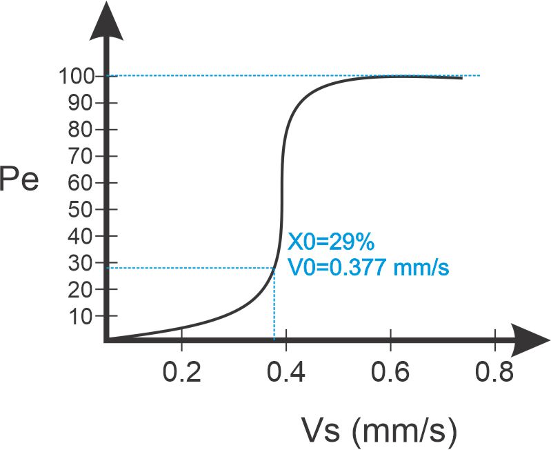
Partial Removal of lighter particle in Sedimentation Tank.
Percentage of particle with Vs < V0 , which shall get removed Pe= (Vs/V0) X 100
In case of upflow tank, no such partial removal will take place.
Test for analysis is done by sieve analysis and hydrometer test.
In all, the particles having settling velocities greater than or equal to V0 , will be full removed and remaining X % will be removed in ratio Vs/V0
So, total percentage of particles removed :

Normally adopted value for V0 = (12 -18) m3/day per m2 plan
Decreasing overflow rate will lead to settlement of even particles of lower VS
Increase in plan area (B X L) increases efficiency of tank. Depth does not have any effect on sediment removed.
Depth range : (3 – 4.5) m
Detention time (T) in Sedimentation tank
Average theoretical time required for water to flow through tank.
\color{blue} \large{t = \frac{Volume \:of \:tank}{Rate \:of \:flow}= \frac{BLH}{Q}}For Circular Tank
\color{blue} \large{t = \frac{d^{2}(0.011d + 0.785H)}{Q}}d : diameter of tank
H : Vertical depth at wall or side water depth.
t = (4 – 8) hrs : Plain tank
t = (2 – 4) hrs : Coagulants used
Width B ∈ 10 m < 12 m
Length L should not be greater than 4B
V = 0.3 m/min
Short Circuited Flow in Sedimentation Tank
If currents permit a substantial portion of water to pass directly through tank, without being detained for intended time, the flow is short circuited.
Properly designed inlet and outlet near entrance and exit may reduce the short circuiting tendencies.
Displacement efficiency = Detention time / Flowing through period
It varies between 0.25 to 0.5 in normal sedimentation basins.
Flow velocity should not be greater than scour velocity or displacement velocity.
Submerged weir type of baffle wall is provided at inlet and outlet arrangement.
Proper cleaning is required time to time as deposited sludge reduces detention time and cause formation of foul gases.
Sludge is scrapped and brought to hopper at outlet for removal.
Tube settlers in sedimentation tank
Attempts are made to place horizontal trays, to reduce depth and to multiply surface area in order to reduce surface overflow rate.
Very small diameter tubes having high wetted perimeters relative to wetted area, provide laminar flow condition and low surface loading rate. Such a tube settling device is called tube settler.
We mostly prefer 60 degrees inclined settlers.
Filtration
In this part we will understand the process of filtration in detail along with learning about different types of filters.

Filtration
Passing of water through the beds of granular material. It helps in removing colour, odour, turbidity and pathogenic bacterial to some extent.
Types of Filters :
- Slow Sand Gravity filter
- Rapid Sand Gravity filter
- Rapid Pressure filter
Types of Filtration :
- Mechanical straining
- Flocculation and Sedimentation : void space act as unit of sedimentation
- Biological Metabolism : The organic compound are utilised by microbes and converted to harmless layer, called Schmutzdecke or dirty skin. This layer further helps in absorbing and straining out impurities.
- Electrolytic changes : It changes the Chemical character of water.
Filter material :
Sand
Obtained from rocks like Quartzite. It should be uniform, dirt free, hard, resistant and should not lose 5 % of weight in Hydrochloric Acid kept for 24 hrs.
The size of sand is measured and expressed by term effective size D10
D10 : Size of sieve in mm through which ten percent of sample of sand will pass.
The sand used in slow sand filter : D10 = (0.2 – 0.4) mm
The sand used in Rapid sand filter : D10 = (0.35 – 0.55) mm
The uniformity in size and degrees of variation in size of particle is expressed as uniformity coefficient.
\color{blue}\large{D_{U}= \frac{D_{60}}{D_{10}}}Slow sand filter : DU = (1.8 – 2.5)
Rapid sand filter : DU = (1.3 – 1.7)
Gravel
- Used below Sand
- Hard, durable and properly rounded
- Density = 1600 Kg/m3
- 3 – 4 layers
- Depth = (15 – 20) cm each
Anthrafilt
Made from Anthracite (Coal)
Types of Filters in Sedimentation tank
Slow Sand Filter
- Invented by James Simpson in 1829.
- It has became obsolete these days.
- Preferred on small plants at warm places.
- It utilizes effluent from plain sedimentation tank. Water should not be treated by coagulation, due to the fact that the dirty skin formed by floc effects the working of this filter.
- Depth of water should be normal and non fluctuating as possible.
- Filtration head has maximum limit of (0.7 – 1.2) m.
- Cleaning : Scrapping and removing the 1.5 to 3 cm of top sand layer. The top surface is finally raked, roughened, cleaned and washed with good water.
- Schmutz Decke : Film of arrested impurities around sand grains. It requires 24 – 36 hrs from cleaning to from and treat. Filtration process is largely dependent upon this film.
- Rate of Filtration : (100 – 200) l/hr/m2
- Extent of bacteria removed = (98-99) %
- It can remove odour, taste but less effective in removing colour.
- Remove turbidity upto 50 mg/l
- Use : Small purification plant.
- Large area need and costly
Construction :
Enclosure Tank
- Open water tight rectangular tanks, made of masonry or Concrete.
- Bed Slope is about 1 in 100 towards central drain.
- Area = (100 – 200) sq. m
Filter Media
- Sand Layer
- Depth : (90 – 110) cm
- D10 = 0.2 – 0.4
- DU = 1.8 – 2.5
- Top 15 cm is of finer sand, and bottom layer is of coarser sand
- More fine sand, More pure water
Base Material
- Gravel
- Thickness = (30 – 75) cm
- 3 – 4 layers
Under Drainage of Tank
Gravel is present as layer under drainage system. Central drain is with lateral drains.
Inlet and Outlet of Tank
It distributes effluent uniformly over filter bed.
Other Tank Appurtenances
Vertical air pipe with meter gauge to measure filter pressure.
Rapid Sand Filters
- Invented by G W Fuller
- 30 times yield of slow sand filter
- Water from coagulation sedimentation tank is in use.
- Two type : Rapid gravity and Pressure filter
- Use : large municipal supplies
- Cleaning : Back washing
- Rate of filtration = 3000 – 6000 l/hr/square m
- Efficiency : less efficient in removing bacteria and very efficient in removal of colour and turbidity.
- Quite flexible to meet variations in demand
Construction
Enclosure Tank
Depth is 2.5 to 3.5 m and has at least two filter units in one plant.
Filter Material
Sand : depth = (60 – 90) m
D10 = (0.35 – 0.55)
DU = (1.3 – 1.7)
Base Material
Use of Gravel as base material which is also helpful in distributing wash water.
Under Drainage of Sedimentation Tank
It receives and collects filtering water and allow backwashing to clean.
Forms : Manifold and lateral, Wheeler bottom, Porous plate bottom and Pipe and strainer.
Compressed air is used along the backwashing.
Other Tank Appurtenances
Wash Water trough : Tank collects the Backwash rising water. It prevents sand boiling.
Air Compressor : Agitate sand grains during backwashing.
Rate controller : At outlet of filter for uniform rate of filtration.
Pressure Filter
- Just like Rapid Gravity filter.
- Water pass under pressure.
- Pumping of water under pressure of (30 – 70) m of water.
- Horizontal or vertical pressure types.
- Coagulant : Alum
- Cleaning : Backwashing
- Rate of filtration : (6000 – 15000) l/hr/square m
- Less efficient than Rapid Gravity in removing bacteria and turbidity.
- Quality of effluent is poor, and hence not used for public supplies.
- Use : Colonies of few house, Private house, Swimming pools and Railway Stations.
Duel Media Filter
- Top layer : Anthracite coal
- Bottom layer : Filter sand
- Top layer is 30 to 60 cm deep and bottom layer is 20 to 40 cm deep.
- In mono medium filters, reverse gradation takes place after backwashing which this filter avoids later.
- Higher filtration rate than Rapid Sand Filters.
Multi Media Filter
- Anthracite coal and sand as top and bottom layers.
- Extra layer of Garnet
- It is improvement over duel media filter.
- Cost is high because of garnet.
- Filtration rate is similar to duel media filter.
Problems in working of Filtration Tank :
Bumping of filter
Careless or indifferent operation of filter cause inadequate cleaning.
Air Binding
When negative pressure develops in filter, formation of bubbles initiates. These bubbles stick to sand and grains, called Air binding. It reduces the filtration capacity.
Remedy :
- Avoid development of excessive negative pressure head by frequent cleaning of filters.
- Controlling growth of algae.
- Precaution against warming of water.
- Remedying condition that super saturate water with air.
Mud Balls
Mud from atmosphere stick to sand surface, to form dense mat. Afterwards, Mud sinks down to sand bed and lower to gravel.
It interferes with upward movement of wash water. They cause turbulence around them and keeps on filling until the entire space in filter box fills.
Remedy :
- Breaking mud balls by mechanical rakes.
- Breaking by wash stream by pointed pipes.
- Compressed air scour during back washing for four minutes
- Soaking of sand in water and caustic soda and agitation by air.
Cracking of Filter
The fine sand in top layer, shrink and form shrinkage cracks in bed, near wall junctions. With use of filter, the loss of head pressure of sand bed increases, causing widening of crack.
The floc, mud and impurities arrested in filters penetrate deep into filter through these cracks, impairing both washing and efficiency.
Remedial measures is same as mud balls.
Water Purification
This part provides us an insight about several processes that helps in removing colour, odour and taste from water to make supply water desirable.
Removal of Colour, Odour and Taste from water
Aeration
Water gets in intimate contact with air, so as to absorb oxygen and remove carbon dioxide. It helps in killing bacteria to some extent and removes hydrogen sulphide gas along with iron and manganese.
Ways of Aeration in Sedimentation Tank
By Spray Nozzles
It breaks water into droplets, thus permitting escape of carbon dioxide (90 % removal). We require Considerable head pressure.
Permitting water to trickle over cascades
Water is made to fall through certain height (1 – 3) m over a series of steps with a fall of about 0.15 to 0.3 m in each step. It is freefall aeration. It is efficient in raising Dissolved Oxygen, but not for removal for carbon dioxide.
Weirs and waterfalls of any kind are examples of cascade aerators.
By Air Diffusion
Compressed air is bubbled through the water, in order to thoroughly mix it with water. Perforated pipes are installed at bottom of settling tanks and compressed air is blown through them.
The compressed air bubbles up and mixes with water.
Using Trickling Beds
Water trickles down beds of coke supported over the perforated bottomed trays, and arranged vertically in series.
Water application from top through perforated distribution pipes and subsequent trickling to bottom which in turn faces aeration.
It also helps in removal of volatile gases and heavy metals.
Too much aeration makes water corrosive, so we need Deaeration
Deaeration by trickling water down in gravel layers in a closed vessel at a pressure of about one-third of atmosphere.
Treatment with Activated Carbon
- Activated carbon can absorb and attract impurities.
- Removes taste and odour.
- Manufactured by charring wood or sawdust at 500 degrees centigrades in closed vessel.
- Granular or powdered form is more used and they are highly porous .
- Helps in removal of phenol type impurities.
- Added to water either before or after coagulation.
- Usual dose : (5 – 20) mg/l
- Regeneration of granular activated carbon by forcing live stream upward through perforated pipes placed in gravel beds of filter.
- It removes chlorine demand, organic matter and aids in coagulation. Its overdose is not harmful.
Treatment with Copper sulphate
- It removes colour, odour and taste.
- Treat water in distribution pipes.
- Kill algae or check its growth.
- Algae gives off oil and other decomposing product, which copper sulphate checks down.
- Dose : (0.5 – 0.65) mg/l
- May harm fish life.
Oxidising agent
- Potassium permanganate : (0.05 – 0.1) mg/l
- Chlorine
- Ozone