
River Training is a method of guiding river through construction of several structures in order to control flow and sediment transport of Rivers.

Sediment Transport Mechanism
In this section we will deal with few terms related to River sediments and also learn about several stages in which rivers go through in the process of sedimentation.
Sediment Transport
Erosion of Sandy and Silty particles takes place and they move along with River and Canal water flow and gets deposited.
It plays pivotal role in building the landscape of rivers, canals and other streams.
- Scouring and Silting may change the flood level.
- May create sharp turns and irregular curves, which increases the flow resistance of channel.
- Storage capacity of reservoir is reduced by Silting.
River Bed Load
Sediment moves along bed with occasional jump into channel.
River Suspended Load
Materials are maintained into suspension due to turbulence.
River and Canal Bed Formation
At low velocity bed does not move at all. When velocity gradually increases, a stage is firstly reached, when sediment load just comes at point of motion (threshold stage of motion).
On further increase of velocity, bed develops ripples of saw tooth type.
Next, larger periodic irregularities appear, called dunes, first superimposed with ripple and later separate whole.
Ripple do not occur if size of bed particles is coarser than 0.6 mm.
Dunes are rounded and larger in size.
When velocity increases beyond formation of dunes, dunes are erased by flow, leaving very small undulations or virtually flat surface with sediment particles in motion.
Further increase in velocity, result in formation of sand waves in association with surface waves.
When V increases such that Froude Number F > 1, flow become super critical, and surface wave become so steep that they break intermittently and move upstream.
Although sediment keep moving downstream only. Sand waves are called anti-dunes (direction of motion is opposite).
Anti dunes stage accounts for high transport rate.
In case of canals and natural streams, anti-dunes rarely occur.

Mechanism of River and Channel Sediment Transport
Assumption :
Soil is incoherent (no cohesive force, C = 0)
Force on sediment particle : Drag or tractive force exerted by water on wetted area.
Average Unit Tractive Force :
\color{blue}\large{\tau _{o} = \gamma _ {w} R S}R = A/P
γw = Unit weight of water
S = channel bed slope
Distribution in trapezoidal section :
Design of Non Scouring stable channel having protected side slope in alluvium : Shield’s entrainment method (critical traction stress is taken)
A hydraulically and economically efficient channel is the one which possesses minimum perimeter for given area.
For Minimum Perimeter (with constant A)
\color{blue}\large{\frac{\partial P}{\partial y}= 0}Design of Channels in India
This part covers the methods and steps involved in design of artificial and stable channels in India. Besides, we will look closely at Few popular Regime theories that are widely prevalent today.
Design of stable River and Artificial channel in India
As long as average shear stress 𝜏o acting on boundary of an alluvial channel is less than critical shear stress 𝜏c , the channel shape remain unchanged.
In India, alluvial channels are designed on the basis of hypothetical theories given by Kennedy and Lacey. These theories are based on experiment and experience gained on existing channels.
If velocity of flow is more, the bed and banks are likely to face erosion.
For less velocity : suspension silt is likely to get dropped.
Scouring lowers the full supply level and cause loss of command. It may cause breaching of canal and failure of foundation of Irrigation structures.
Silting interferes with proper working of channel, as channel section gets reduced by siltation, reducing discharge capacity.
Regime Channel
A channel is said to be in state of regime if silting and scouring need no special attention. It is impractical case.
Velocity employed is critical velocity where no silting and scouring occurs.
Kennedy’s Theory (1895)
R G Kennedy, an Executive Engineer of Punjab, PWD, carried out extensive investigation on some of the canal reaches in the Upper Bari Doab Canal System.
His observations
- He concluded that silt supporting power in channel cross section was mainly dependent on generation of eddies, rising to surface.
- These eddies are generated due to friction of flowing water with channel surface. The vertical component of these eddies try to move sediment up, while the weight tries to put them down, keeping sediment in suspension.
- If velocity is sufficient to generate these eddies, silting will be avoided. He defined critical velocity (Vo), and related it to depth of flow (y).
\color{blue}\large{V_{o} = 0.55 my^{0.64} }Vo is in m/s and y is in meter.
m = critical velocity ratio (CVR) = Mean velocity Va / Vo
\color{blue}\large{V_{a} = \frac{V_{0.2y}+V_{0.8y}}{2}}| Values of m | Soil |
|---|---|
| 1 -1.2 | Coarser Sand |
| 1 – 0.7 | Finer Sand |
| 0.7 | Silt |
| 1 | Sandy Silt |
| 1.2 | Sandy loamy Silt |
| 1.3 | Debris of hard rock |
Design Procedure :
Kutter’s Formula
\color{blue}\large{V = \left [ \frac{\frac{1}{n}+(23 + \frac{0.00155}{S})}{1 + (23 + \frac{0.00155}{S})\frac{n}{\sqrt{R}}}\right ]\sqrt{RS}}Manning’s Formula
\color{blue}\large{V= \frac {1}{n}R^{\frac{2}{3}}S^{\frac{1}{2}}}n : manning’s rugosity coefficient
R = A/P
S : bed slope
| Condition of Channel | n |
|---|---|
| Very Good | 0.0225 |
| Good | 0.025 |
| Indifferent | 0.0275 |
| Poor | 0.030 |
Chezy’s Formula
\color{blue}\large{V= C\sqrt{RS}}C : Constant depending upon shape and surface of channel.
Kutter equation is used with Kennedy Theory.
Design Step :
- Critical Velocity : Vo = CmDn = 0.055my0.64
- Assume D (1.8 m or so)
- Find Vo
- Find A = Q/V
- Assume Side Slope (1/2 : 1)
- Actual Velocity is found using Chezy and Kutter formula
\color{blue}\large{A = y \left (b + y \frac{1}{2} \right )}\color{blue}\large{P = b + \frac{D}{\sqrt{5}}}\color{blue}\large{R = \frac {A}{P}}If V = Vo : Assume depth is right, else continue again.
Use of Garret Diagram
In order to save mathematical calculation, graphical solutions of Kennedy and Kutter Equations were developed by Garret.
Lacey’s Theory (1939)
An eminent Civil Engineer of U.P irrigation Department carried out research on stable channel in alluvium. He found many drawbacks in Kennedy theory.
Lacey’s Regime Channel
Even a channel showing no silting and scouring may actually not be in regime. He differentiated three regimes condition.
True Regime
- No silting and scouring.
- Artificial channel with constant flow, discharge, silt charge and silt grade
- Channel flowing through medium of incoherent alluvium.
- In practice, Artificial channel can never be in true regime.
Initial Regime
- When only bed slope of a channel varies due to dropping of silt.
- Its cross section or wetted perimeter remain unaffected, even then the channel can exhibit no silting, no scouring properties.
- It is then called Initial Regime
- They have achieved a working stability due to rigidity of these banks
- They have narrow cross section, high slope and velocities.
- Regime theory is not applicable to them as they are in fact, not channels in alluvium
- Bank soil : grassed or of clayey soil; may not get eroded.
Final Regime
- If no resistance is from sides, to allow variation in parameters, then channel finally gets adjusted according to discharge and silt grade.
- Then the channel is said to have achieved permanent stability, called Final Regime.
- Regime theory is applicable to such channel only.
- Channel has tendency to assume a semi-elliptical section. The coarser the silt, the flatter is the semi-ellipse. The finer the silt, more nearly the section attains a semi-circle.
Lacey Theory
- Sediment is kept in suspension not only by vertical component of eddies generated on channel body, but also by eddies generated on the side of channel.
- Silt supporting power of channel is proportional to wetted perimeter of channel, not its width.
- Grain size of material forming channel is important factor. He introduced term, called silt factor (f) and connected it to average particle size.
\color{blue}\large{f = 1.76 \sqrt{d_{mm}}}Design :
\color{blue}\large{V(m/s)=\left [ \frac{Qf^{2}}{140} \right ]^{\frac{1}{6}} m/s }\color{blue}\large{R = \frac{5}{2}\left ( \frac{V^{2}}{f} \right ) }\color{blue}\large{A = \frac{Q}{V} }River and Channel Wetted Perimeter
\color{blue}\large{P = 4.75\sqrt{Q} }River and Channel Bed Slope
\color{blue}\large{S = \frac{f^{\frac{5}{3}}}{3340Q^{\frac{1}{6}}}}Assume slope to be 1/2 : 1
A = BD + D2/2
P = B + D/√ 5
Lacey Regime width
\color{blue}\large{W = 4.75\sqrt{Q} }Since for wide channel, wetted perimeter is approximately equal to width.
Regime scour depth :
\color{blue}\large{R'_{r}=0.473\left [ \frac{Q}{f} \right ]^{\frac{1}{3}} m/s }| Soil | dm |
|---|---|
| Fine silt | 0.05 – 0.08 |
| Standard silt | 0.32 (f=1) |
| Medium sand | 0.51 |
| Coarse sand | 0.73 |
| Gravel | 7.28 |
| Boulder | 72.5 |
Assumption
- Q is constant
- Silt charge and silt grade is constant
- Unlimited incoherent alluvium of same alluvial characters as that of transported
| Kennedy | Lacey |
|---|---|
| Trapezoidal section | Cup shaped |
| Side eddies has horizontal movement greater part and has no contribution | Include side eddies effect |
| Derivation in terms of y | Derivative in terms of hydraulic Mean radius R |
| Use Kutter formula for V | Developed general regime flow equation. |
Lining of Irrigation Canal
Lining means earthen surface of channel is lined with stable, surface of concrete, tiles, asphalt etc. The seepage losses can be reduced to 2 – 5 % of original values.
Advantages :
- Seepage control
- Prevention of waterlogging
- Increase in channel capacity (less resistance to flow)
- Increase in command area : steeper gradients can be provided with small cross section and lengths
- Less maintenance cost
- Less flood danger (less breach)
Design :
- Triangular Channel : for small discharge
- Trapezoidal section : large discharge. In order to increase A/P ratio, corners are rounded and attempts are made to use deeper section by limiting depth.
Permissible velocity (unreinforced lining) = upto 2.5 m/s
Free board = 0.75 m (main canal), 0.6 m (Side canal)
Bank width = 8 m
Thickness = (5-15) cm of cement concrete for large canal
Types of lining
- Shotcrete lining : cement mortar (1:4) applied under pressure through nozzle
- Asphalt concrete lining : Asphalt with graded stone aggregate at high temperature
- Boulder lining (dry stone or pitching)
- Tile or brick
- Compacted earth lining (30 – 90) cm thick
- Soil-cement lining
River Types and Features
In this section we will come across several types of river on basis of topography and hydrography. We will also deal with few features of rivers based on their Behaviour.
Rivers, Their behavior control and training
Classification of Rivers on basis of topography
- Rivers in hills (upper reaches)
- Rivers in alluvial plains (lower reaches)
- Tidal rivers
Stages of Rivers in hills
- Rocky or incised river stage : flow channel is generally formed by process of degradation (erosion). Their reaches are highly steep with swift flow, forming rapids along the courses.
- Boulder river stage : river bed consists of mixture of boulder, gravel, shingles and alluvial sand deposits, created by itself. River flow through wide shallow beds and interlaced channels, and develop a straighter course.
- Rivers in alluvial flood plain (lower reaches) : They are in zigzag fashion and meandering. Materials get eroded constantly from concave banks (outer edge) of bend and get deposited on convex side.
Types of Rivers on the basis of silting
- Aggrading : river is collecting sediment and building up its bed.
- Accreting type
- Such rivers increase its bed slope
- Usually has straight and wide reaches with shoals in middle.
- Degrading : bed is getting scoured year by year, in order to reduce and dissipate available excess land slope. It may form either above a cutoff or below a dam or barrage area. Colorado river in USA is great example.
- Stable type : the river doesn’t change its alignment, slope and its regime significantly. Negligible silting and scouring due to which entire sediment reaches the sea.
- Braided river : when river flows in two or more channels around alluvial islands, formed by local deposition of coarser material.
- Deltaic river : river joining sea divide into several branches, forming a triangle shaped land called delta
- Tidal rivers : the tail reaches of the river is affected by tides. Ocean water enters the river during flood tide. They show periodic rise and fall.

Types of Rivers on the basis of Hydrography
- Flashy river : Sudden rise and fall in flood level due to which the flood hydrograph is very steep.
- Virgin river : In arid desert, a river may get completely dry before getting into sea because of excess evaporation and percolation.
Behaviour of River
Straight Reaches
River cross section is in the shape of trough with high velocity flow in the middle of the section.
Transverse rotary currents develop in these channels.
River Bends
Characterised by scouring on concave side and silting on convex side, under action of centrifugal force.
When flow move round a bend, a centrifugal force is exerted upon water which result in formation of slope of water surface from convex edge to concave edge.
Rotary currents are formed that form shoals on convex side.
Meanders
Formation of successive bends of reverse order. (follow sine curve)
Cause: extra turbulence generated by excess of river sediment. It causes river to deposit silt on bed which increases river slope and width.
If banks are not resistant, one bank will be attacked slightly more than other, causing slight deviation of flow. Now, silting and scouring cycle starts.
Four Variables that governs River meandering process
- Valley slope
- Silt grade and Silt charge
- Discharge
- Bed and Side material and their susceptibility to erosion.
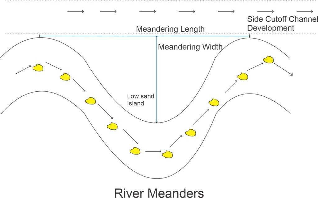
\color{blue}\large{Meander \: ratio = \frac{M_{B}}{M_{L}}}\color{blue}\large{Dominant \: discharge =\frac{1}{2} or\frac{2}{3} Q_{Max}}
Tortuosity
Rate of length along channel (arch length) to the direct axial length along the river reach.
Steep rivers meander to a lesser extent compared to that with flatter gradient.
Meanders increase river length.
Cutoff
A particular bed may be abandoned by formation of straight and shorter channel. The chord channel is termed as cutoff.
Cut off reduces river length.
Development :
During high floods, excessive deepening of pools occurs, and is supplemented by growth of bars at the inflection. Both these factors tend water to flow more and more towards the side channel.
It may take 6 months per year, or 5-10 years to chord channel to develop completely.
Cutoff ratio : ratio of length of bend to that of chord
Conditions for development of cutoff :
- Cutoff ratio varies fro 1.7 to 3
- Ratio : r/√Qmax = 13 to 24, where r = radius of curvature of loop and Q is discharge.
- Shallow side channel is tangential to the main direction of river approaching and leaving the cut.
Angle of Swing
It is angles in degrees by which flow takes a turn.
Maximum possible angle of swing :
\color{blue}\large{\theta = 180\degree + 2\left [ \sinh^{-1} \left ( \frac{chord}{2 \times Radius} \right ) \right ]}Control and Training of River
This section gives proper details of various methods to control River courses along with explanation of few hydraulic structures that are used in training of Rivers.
Control and Training of River
All Water Resource Engineering works constructed on a river, so as to guide and confine the flow to the river channel, and to control and regulate the river bed configuration.
Classification
High water training (Training for discharge)
- For Flood control
- Involve providing sufficient cross section for safe passage of floods and construction of dyke, levee etc.
Low water training (Training for depth)
- Provide sufficient water depth for navigation
- Can be achieved by enhancing flow or by process of bandalling by contracting the width of channel with the help of groynes etc.
Mean water training (Training for sediment)
- Efficient disposal of suspended load and bed load.
- To Preserve channel in good shape.
- Maximum accretion capacity of river occurs in vicinity of mean water or dominant discharge.
- It acts as base for previous trainings.
Khadirs : The extreme lines within which river is ever known to wander.
Meandering type is full and final development of an alluvial river.
Aggrading rivers are not suitable for training as it is unstable.
Training on degrading rivers may fail due to scour of foundation . The scouring action can be controlled by building cross bays and weirs etc.
General Methods of River Training
Marginal Embankments or River Levees
- They are earthen embankments running parallel to river at some suitable distance.
- They retain flood water.
- Mainly used for flood protection, not by training rivers but by controlling rivers.
- Pitched on upstream side. Launching aprons are also provided.
- Top width : (2.5-10) m
- Free board : (0.3-1.5) m
- Seepage gradient must be inside body.
- Reduction in velocity and silt deposition will be less in diked river, as spread area is less.
- Bed level of river and enclosed area rise.

Guide banks
It is unwise and uneconomical to span entire width of river and expose structures to vagaries of attacks and deep scour. Hence, structures are extended in a smaller width of river.
The river is trained to flow axially through this trough without outflanking.
This is achieved by Guide Banks.
- Guide banks are generally provided in pairs, symmetrical in plan. It may be kept parallel or diverge slightly upstream.
- It consists of two heavy embankments in shape of bell mouth. Portion of river between normal river bank and guide bank are closed by ordinary embankments.
- Selection of site : where distance between khadir bank is minimum.
- Amount of afflux : 1-1.2 m
- Divergent banks induce oblique flow and tend to form shoals in the center. They exercise attracting influence to flow and are suitable for oblique flows.
- Length of guide banks : 1.2 L (Upstream); (0.1-0.2) L (Downstream)
- Radius of curved head of guide banks : R = 0.45 L (Upstream) ; R1 = R/2 (Downstream)
- Angle subtended at center θ = (45 – 60)° for Downstream and (120-140)° for Upstream.
- Upstream curve : Impregnable head
- The straight portion is called shank.
- Minimum Top width : 4 m
- Side Slope = 1.5 : 1, 2.5 : 1
- Free board : 1.2 – 1.5 m
- Slope pitching : pitching should extend 1 m higher than HFL
- Thickness of pitching = t = 0.06Q1/3
- Provide 25 % more pitching at impregnable head.
- Short guide bund with sharp curve head is provided in order to protect from attack of fanning out river.

Launching Apron
Pitching extended beyond the toe on bed in form of packed stones. This stone dumping is called launching apron.
Scour will occur at toe with subsequent collapse of stone pitching.
Width of launching apron = 1.5 X depth of scour (D)
Lacey normal scoured depth R = 0.47(Q/f)1/3
Q : Discharge ; f : silt factor
D = xR – y
y : water depth
Thickness of launching apron T = 1.9t
t : thickness of pitching

Spurs and Groynes
- Groynes are embankments type structures constructed transverse to river flow, extending from bank into river.
- They are also called transverse dykes.
- They protect banks by deflecting the current away from bank. As water is unable to take sharp embayments, the bank get protected from some distance upstream and downstream of groynes.
Types of alignment of Groynes in River
- Ordinary or Normal Groynes : perpendicular to bank, used for convex banks.
- Repelling Groynes
- pointing upstream
- angle : (10 – 30)° with normal to bank
- repel the flow away
- scour holes are developed away from bank and near head of groynes
- when its length is very small, they only change direction flow and are called deflecting groynes.
- used for concave banks
- Attracting Groynes
- point downstream
- attract flow towards it
- scour holes are developed near the banks, making it more susceptible to erosion.
- used to attract water towards guide banks.
Groynes need heavy pitching protection and apron by loose stones filled in wire crates.
Constructed in series : more effective and form a pool of almost still water with heavy silting forming a new bank.
Spacing is dependent upon
- length
- type of bank : convex – more spacing
- width of river : more width, more spacing
- type of groynes : more spacing for permeable groynes

Types of Groynes
- Impermeable Groynes
- Solid embankment groynes
- do not allow significant flow through them.
- rock fill embankment or earthen embankment armored with stone pitching, concrete blocks etc.
- Permeable Groynes
- permit restricted flow through them
- temporary structures susceptible to damage by floating debris
- materials used : tree, timber stakes, wooden piles, stone filled balli crates, stone filled in wire crates
- suitable for river carrying huge sediment load in suspension
- do not generate so strong turbulence and change flow abruptly
- wood used for balli spur : Sal
- giver better result in submerged position
- cheaper
- T shaped Groynes
- ordinary groyne with extra cross groyne at head
- cross groyne protect main groyne
- Hockey shaped
- turned at lower end
- exert attracting type of influence
Artificial River Cut offs
For inducing an artificial cut off only a pilot channel is required to be excavated for easily erodible beds. The flood water will gradually enlarge the pilot cut to required cross section, and abandon the old curve.
Side pilot channel will be self scouring if (R/L2) greater for cut than the original course. (R = A/P ; L : length along the course)
- Cut off channel should be deeper and more hydraulically efficient. Tractive force is directly proportional to depth.
- Width of cut is less important.
- Alignment of cut should be tangential to the main direction of flow approaching and leaving the cut.
- Pitching of bank and Launching Apron
- Type : stone, concrete blocks, brick lining, vegetation cover etc.
- Stable slope of 1:1 to 2:1
- Launching apron to prevent scour at toe.
- Pitched Island
Artificial River Island
Artificially constructed island with stones pitching all around.
Turbulence creates river channel around island and get deepened, then attracting the river towards itself, and hold it permanently.
It helps in attracting the current to reduce undue concentration on opposite bank.
Miscellaneous
Submerged Dyke
Placed across scoured portions of bed, with their top level at or slightly below the design bed level.
Closing Dyke
To close particular flow to direct river in other desired direction.